PreSonic Install Guide
Introduction
Welcome to the PreSonic installation Guide. This guide is specifically designed for a seamless upgrade, assuming your guitar is currently equipped with a standard Fishman™ side-mounted preamp system. Because the necessary side cutout and endpin jack hole are already present in your instrument, no major structural modification to the guitar body is required.
However, the PreSonic system utilizes high-fidelity, ultra-low-profile flex cables and specialized latching connectors that differ from traditional systems.
Before you begin, please put your tools down and carefully study the Connector Anatomy section; success with this installation depends entirely on the gentle handling of these components rather than force.

If you have any questions, please contact us.

DO NOT force anything.
Required Tools
- Drill
- #1 Phillips screwdriver
- #2 Phillips screwdriver
- 1/4” (6.35mm) dowel rod
- flush-cut wire cutters
- 1/2” open end wrench or adjustable wrench
- Slip-joint pliers
- Sanding materials and shaping tools (belt sander preferred) (only required if you are shaping the Saddle-Pickup)
- Masking tape
- Black permanent marker
- Pencil
- Ruler
- Flashlight
- acoustic guitar amp or PA system
- 1/4” guitar cable
- 9v battery for the preamp
Package Contents
A. PreSonic Preamp (Small size shown)
B. Zip Tie
C. Black screws (5)
D. Silver screws (2)
E. Cable clips (4)
F. Cable guide tube (2)
G. Inside mounting bracket (2)
H. Battery bracket cable clamps (2)
I. Installation Tool
J. Output jack assembly
Saddle-Pickup Kit
Steel-StringNylon-StringSteel-String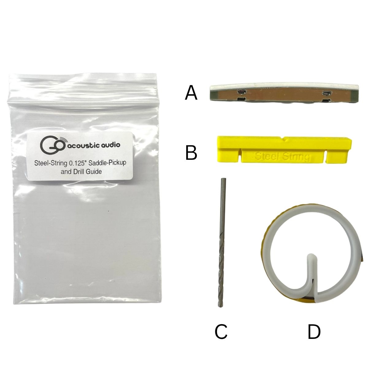 Steel-String Saddle-Pickup Kit
A. Saddle-Pickup
B. Drill GuideC. 2.8mm Drill BitD. Pickup Cables on a spoolNylon-String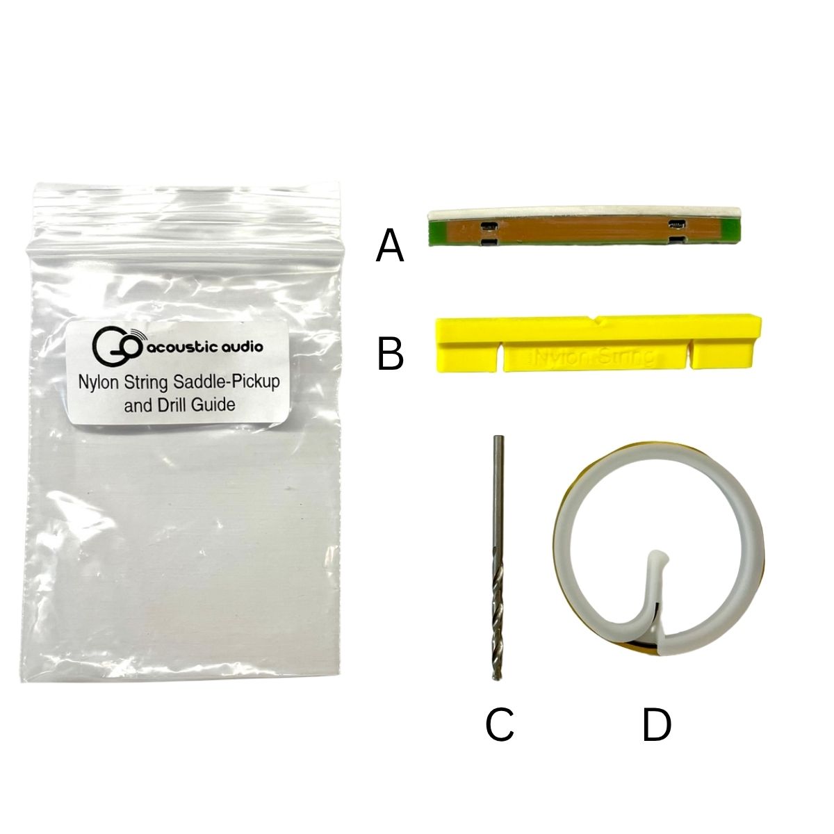 Nylon-String Saddle-Pickup Kit
A. Saddle-Pickup
B. Drill GuideC. 2.8mm Drill BitD. Pickup Cables on a spool
Steel-String
Nylon-String
Steel-String
A. Saddle-Pickup
B. Drill Guide
C. 2.8mm Drill Bit
D. Pickup Cables on a spool
Nylon-String
A. Saddle-Pickup
B. Drill Guide
C. 2.8mm Drill Bit
D. Pickup Cables on a spool
Connector Anatomy & Handling
WARNING!!!!
STOP: VISUAL STUDY ONLY Please put your tools down.
The following steps outline the Standard Operating Procedure for the PreSonic Saddle-Pickup cable connectors. You will need to perform these exact actions later in the installation.
For now, read through the steps to mentally rehearse the motion. Do not physically attempt these connections until instructed to do so in the "Installation" section.
Study the "Up" (Open) and "Down" (Locked) positions below. You must understand the latching mechanism before handling the actual installation.

Make sure you understand the connector latch positions. The same connectors are used on both the Saddle-Pickup and the preamp.
Up: Make sure the connector latch is in this position when you are inserting or removing a cable.
Down: This position clamps down on the cable to hold it securely in the connector. Make sure to push the latches down after inserting the cable.
Saddle-Pickup Connectors
Mechanism Overview: Insertion
1. Ensure that the connector latch is in the open position.
2. Ensure that the cable is oriented properly.
- The end labeled “Pickup” must plug into the connector on the pickup.
- The gold side of the cable end faces the access opening on the pickup.
3. Gently insert the cable end into the connector up to the "Flush" line.
- Do Not force the cable if there is resistance.
- Gently wiggle the cable until it aligns into the connector.
- When it is properly aligned, it will require almost no force to insert it.
4. Gently close the latch on the connector as shown in the animation.
5. Gently pull on the cable. It will not pull out if properly seated with the latch closed.
Mechanism Overview: Removal
1. Gently insert the small end of the supplied Installation Tool into the small access port behind the flip latch.
2. Gently push the tool further into the access port to push the flip latch open.
3. Gently pull the cable out of the bottom of the Saddle-Pickup.
Preamp Connectors
Mechanism Overview: Insertion
1. Ensure that the connector latch is in the open position.
2. Ensure that the cable is oriented properly.
- The end labeled “Preamp” must plug into the connector on the preamp.
- The gold side of the cable end faces away from the circuit board on the preamp.
3. Gently insert the cable end into the connector up to the "Flush" line.
- Do Not force the cable if there is resistance.
- Gently wiggle the cable until it aligns into the connector.
- When it is properly aligned, it will require almost no force to insert it.
4. Gently close the latch on the connector.
- Using the large blade on the Installation Tool, push the latch down from the side as shown in the animation.
5. Gently pull on the cable. It will not pull out if properly seated with the latch closed.
Mechanism Overview: Removal
1. Carefully open the connector as shown in the animation below.
- Slide the large blade of the Installation Tool under the black latch from the side.
- Rotate the Installation Tool Clockwise so that it pushes the latch open.
2. Gently pull the cable out of the connector.
Preparing the Guitar
In this section you will prepare the guitar for the installation of the PreSonic
- Remove the guitar strings.
- Remove the original saddle and pickup and set aside for measurements.
Installing the Output Jack
In this section you will install the Output Jack Assembly (Part J) into the guitar.
- Remove the strap button, small nut, and small washer from the Output Jack Assembly.
- Use the original jack as a reference to set the distance between the large nut and washer and jack shoulder.
- Insert a dowel rod into the guitar through the jack hole.
- Insert the dowel rod into the jack.
- Pull the jack into place.
- Measure the distance between the shoulder of the jack and the side of the guitar. It should be 1mm. If it is not, push the jack back to the sound hole and adjust the nut on the barrel of the jack.
- Pull the jack back into place and re-measure.
- Repeat until the distance is 1mm.
- Install the nut and washer over the end of the dowel rod and tighten them finger tight on the jack.
- Insert the big blade on the Installation Tool through the small holes on the jack and use a wrench to tighten the nut.
- Install the strap button.
Installing the Inside Mounting Bracket
In this section you will install the Inside Mounting Bracket (Part G).
- Note the Inside Mounting Bracket orientations in the image above.
- Remove the adhesive liner from one of the Inside Mounting Brackets.
- Attach the first Inside Mounting Bracket
- Put a Black Screw (Part C) in one of the mounting holes.
- Carefully insert the Mounting bracket and start screwing the screw into it.
- Make sure that the adhesive does not contac the guitar yet.
- Carefully start the other screw into the bracket.
- Once both screws are started, press the Mounting Bracket against the side of the guitar, using the screws to ensure the holes are aligned.
- Remove the Black Screws.
Align the Inside Mounting Bracke with Black Screws
- Repeat Step 3 for the other Inside Mounting Bracket.
Saddle-Pickup Installation
In this section, you will prepare the guitar bridge for Saddle-Pickup installation. If you have not ordered a pre-shaped Saddle-Pickup, then you will also shape it to fit. Finally, you will install the Saddle-Pickup into the guitar bridge.
1. Prepare the drill guide by reaming out the holes (0.125” Saddle Only)
A. Install the provided drill bit into the drill.
B. Hold the drill in one hand and the drill guide in the other.
C. Slowly ream out each hole.
2. Mount the drill guide to the bridge.
 Aligning the Drill Guide
A. Place Masking tape on the bridge between the saddle slot and the bridge pin holes or tie block.
B. With a pencil, mark the centerlines of the two outside strings using the bridge pin or tie block holes.
C. Measure and mark the halfway point between the two outside strings. This is the neck centerline.
D. Insert the drill guide into the saddle slot and align the notch with the neck centerline mark.
E. Tape the drill guide in place.
3. Drill 2 cable access holes in the bottom of the saddle slot.
0.125" Saddle-Pickup0.100" Saddle-Pickup0.125" Saddle-Pickup Drilling the Bridge Holes 0.125" SaddleA. Insert the drill bit into one of the holes in the drill guide until the bit rests on the bottom of the saddle slot.
B. Press down on the drill guide to keep it from lifting as you drill.C. Slowly spin the bit and drill through the bottom of the saddle slot.D. Repeat the process for the second hole.E. Remove the drill guide.E. If you purchased a pre-shaped Saddle-Pickup, remove the masking tape from the bridge and skip to Step 6.0.100" Saddle-Pickup Drilling the Bridge Holes 0.100" Saddle
Each Access Hole requires 3 drill holes in order to create a wide enough hole for the cable to fit through.
A. Press down on the drill guide to keep it from lifting as you drill.B. Drill the angled holes first. Slowly spin the bit and drill through the bottom of the saddle slot. Make sure to keep the bit straight in the hole so you don’t hit the side of the saddle slot. The notches on the side of the drill guide show you the correct angle of the bit.C. Drill the vertical hole. Slowly spin the bit and drill through the bottom of the saddle slot. Make sure to keep the bit straight in the hole so you don’t hit the side of the saddle slot.D. Repeat this process for the second Access Hole.E. If you purchased a pre-shaped Saddle-Pickup, remove the masking tape from the bridge and skip to Step 6.
0.125" Saddle-Pickup
0.100" Saddle-Pickup
0.125" Saddle-Pickup
A. Insert the drill bit into one of the holes in the drill guide until the bit rests on the bottom of the saddle slot.
B. Press down on the drill guide to keep it from lifting as you drill.
C. Slowly spin the bit and drill through the bottom of the saddle slot.
D. Repeat the process for the second hole.
E. Remove the drill guide.
E. If you purchased a pre-shaped Saddle-Pickup, remove the masking tape from the bridge and skip to Step 6.
0.100" Saddle-Pickup
Each Access Hole requires 3 drill holes in order to create a wide enough hole for the cable to fit through.
A. Press down on the drill guide to keep it from lifting as you drill.
B. Drill the angled holes first. Slowly spin the bit and drill through the bottom of the saddle slot. Make sure to keep the bit straight in the hole so you don’t hit the side of the saddle slot. The notches on the side of the drill guide show you the correct angle of the bit.
C. Drill the vertical hole. Slowly spin the bit and drill through the bottom of the saddle slot. Make sure to keep the bit straight in the hole so you don’t hit the side of the saddle slot.
D. Repeat this process for the second Access Hole.
E. If you purchased a pre-shaped Saddle-Pickup, remove the masking tape from the bridge and skip to Step 6.
4. Cut the Saddle-Pickup to length
 Cut the Saddle-Pickup to length
Cut the Saddle-Pickup to length
A. The Saddle-Pickup is directional. On one side, there are six small vent slots where the white and black material meet. This side faces the bridge pins or tie block.
B. Cover these vents with a piece of masking tape.
C. Mark the center of the Saddle-Pickup on the masking tape.
D. Align the center of Saddle-Pickup to the centerline on the bridge and mark how much length needs to be removed from each end so it will fit in the saddle slot.
E. Grind the ends of the of the Saddle-Pickup to length.
5. Shape the Saddle-Pickup
Steel-StringNylon-StringSteel-String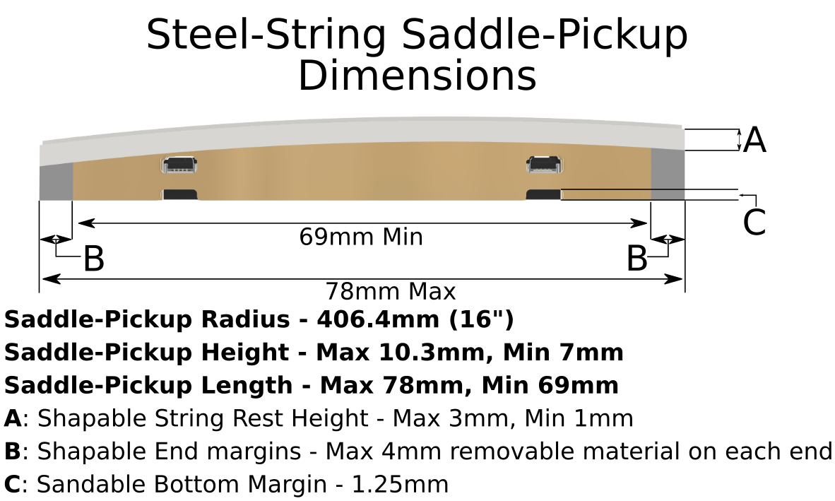 Steel-String Saddle-Pickup DimensionsA. Use the pervious saddle (and pickup if one was installed) as a template to shape the Saddle-Pickup with 120 grit sand paper. If the guitar already had a pickup in it, make sure to account for the thickness of the pickup when calculating saddle height. Only the A and B dimensions shown in the figure may be shaped.B. After the Saddle-Pickup has been shaped, polish the white part of the Saddle-Pickup using sandpaper down to 1500 grit.Nylon-String
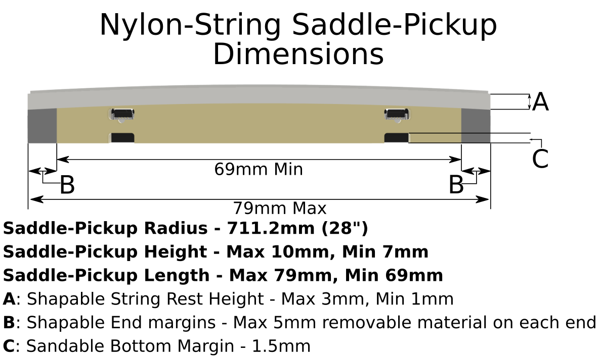 Nylon-String Saddle-Pickup DimensionsA. Use the pervious saddle (and pickup if one was installed) as a template to shape the Saddle-Pickup with 120 grit sand paper. If the guitar already had a pickup in it, make sure to account for the thickness of the pickup when calculating saddle height. Only the A and B dimensions shown in the figure may be shaped.B. After the Saddle-Pickup has been shaped, polish the white part of the Saddle-Pickup using sandpaper down to 1500 grit.
Steel-String
Nylon-String
Steel-String
A. Use the pervious saddle (and pickup if one was installed) as a template to shape the Saddle-Pickup with 120 grit sand paper. If the guitar already had a pickup in it, make sure to account for the thickness of the pickup when calculating saddle height. Only the A and B dimensions shown in the figure may be shaped.
B. After the Saddle-Pickup has been shaped, polish the white part of the Saddle-Pickup using sandpaper down to 1500 grit.
Nylon-String
A. Use the pervious saddle (and pickup if one was installed) as a template to shape the Saddle-Pickup with 120 grit sand paper. If the guitar already had a pickup in it, make sure to account for the thickness of the pickup when calculating saddle height. Only the A and B dimensions shown in the figure may be shaped.
B. After the Saddle-Pickup has been shaped, polish the white part of the Saddle-Pickup using sandpaper down to 1500 grit.
6. Connecting the pickup cables
 Connecting the Cable to the Saddle-Pickup
A. Ensure that the connectors on the Saddle-Pickup are open (the black latches flipped up).
B. CAREFULLY insert the cable end labeled “Pickup” into the 1-3 Saddle-Pickup connector.
C. Use the small blade of the install tool to CAREFULLY flip the latch down.
D. Repeat steps B and C for the 4-6 connector.
E. Mark the “Preamp” end of the 1-3 Pickup cable with a permanent marker. This will allow you to identify which cable is which.
7. Installing the Saddle-Pickup in the Bridge
- CAREFULLY insert the cables through the holes in the bottom of the saddle slot.
- Make sure the cables don’t kink.
- Make sure the Saddle-Pickup is properly oriented with the connector access windows facing the sound hole.
- CAREFULLY seat the Saddle-Pickup in the bridge. Make sure not to kink the cables.
Mounting the Preamp
In this section, you will connect the Saddle-Pickup cables and jack cable to the preamp and then mount the preamp in the guitar.
Prepare the Cable Clips
- Using wire cutters to make a cut in each of the 4 Cable Clips (Part E) as shown below.
Cut the Cable Clip
- Mount the two Cable Guide Tubes (Part F) into two of the cable clips (Part F) as shown below.
Cable Clip with Cable Guide Installed
Connect the Saddle-Pickup Cables to the Preamp
- Carefully pull the Saddle-Pickup Cable ends out of the side cutout where the preamp will go.
- Feed both Saddle-Pickup Cables through both cable guide tubes as shown below.
- Feed the Saddle-Pickup Cables through the small slot in the preamp as shown below. Make sure that the side of the cables with the word "Preamp" is facing the preamp.
Insert the cables through the slot in the preamp
The text "Preamp" should be facing the preamp
- Carefully bend the 1-3 cable in the direction shown below, insert it into the connector, and close the latch
- Make sure the connector is open
- refer to the earlier section to see how to connect the cable to the connector.
Connect the Cable to the Preamp
- Carefully thread the cable through the slots in the side of the battery bracket as shown below.
Thread the cable through the slots
- Secure the cable in place with a Battery Bracket Cable Clamp (Part H) and a Silver Screw (Part D) as shown below.
Secure the Saddle-Pickup Cable in the battery bracket
- Repeat Steps 4 through 6 for the 4-6 cable.
- Carefully pull both cables up as shown below to minimize slack between the battery bracket and cable slot.
Minimize slack
Connect the Jack Cable
- Make sure that the Jack Cable is closer to the back of the guitar and does not pass between the Saddle-Pickup cables and the guitar top.
- Insert the Jack Cable Connector in tho the Jack on the preamp as shown below
- The black wire should on the outside of the preamp
- Use the large end of the Installation Tool to push the connector into place
Connect the Jack Cable
- Check that the system works
- Temporarily install a battery into the preamp.
- connect the system to an amp.
- Tap on each end of the Saddle-Pickup. You should hear sound.
- If you do not hear sound. First, check the master volume control on the preamp. Second, chek that you have made all the cable connections correctly.
- Remove the battery.
- Insert the Zip Tie (Part B) through the inside hole by the Jack Cable as shown below.
Insert the Zip Tie
- Thread the Zip Tie end through the outer hole and through the Zip Tie lock. Pull the tie tight.
Tighten the Zip Tie
- Cut the excess off the Zip Tie. Make sure not to cut anything else!!
Mount the Preamp in the Side
- Carefully place the Preamp in the side of the guitar. Make sure the Jack Cable is closest to the back and the Saddle-Pickup Cables are closest to the soundboard (top) as shown below.
Cable Orientation
- Install two Black screws (Part C) in the two mounting locations closest to the waist but do not fully tighten them.
Install the Black Screws near the waist
- Open the Preamp door and then install the two Black Screws (Part C) in the other two mounting holes.
Open the Door and Install the Other Mounting Screws
- Carefully tighten all four black mounting screws.
Installed Preamp
Cable Management
Install Saddle-Pickup Cable Clips
- Carefully reach inside the guitar through the sound hole and locate the Cable Guide Tube with Cable Clip closest to the bridge
- You can increase the slack in the cables by opening the door on the preamp.
- Mount this Guide Tube in location A (shown above). This should be under the corner of the bridge nearest the preamp.
- Make sure the not to mount the Guide tube too close to a brace to prevent the cables from rattling against it.
- Mount the second Cable Guide Tube in location B (shown above)
- Location B should be somewhere in the waist.
- When the door is open, make sure there is a gentle curve in the Saddle-Pickup Cables and that they are not pulled tight (see the below image). Choose Location B accordingly.
Make sure there is slack in the cables when the door is open
Install the Jack Cable Clips
- Mount a Cable Clip (Part E) in location C (shown above).
- this location should be below the location B Cable Clip (closer to the back)
- Place the Jack Cable in the clip and make sure it is not pulled tight with the preamp door open (see previous image).
- close the Cable Clip
- Mount a Cable Clip (Part E) in location D (shown above).
- Choose this location so that the cable is tight between the jack and location C and will not rattle.
Adjusting the String Balance
- Plug the guitar into an amplifier and make sure the PreSonic and amplifier EQs are set flat and the volume is at a reasonable level.
- Make sure the Mic volume is OFF
- Play a chromatic scale starting on the low E string and note any strings that sound louder than the others.
- Open the preamp door and remove the battery to access the string volume potentiometers. The 1 potentiometer corresponds to High E, and 6 corresponds to Low E.
- Adjust the loud strings down until they are more balanced.
- Play a chromatic scale starting on the low E string and note any strings that seem to be quieter than the others.
- Repeat Steps B through E until you are satisfied.
- Play chords, arpeggios, scales, and songs to ensure the guitar response is accurate. Take as much time as you need to get the results you want.
Save the spare flex cable and Installation Tool. Keep these in your guitar case since they may be needed in the future for system maintenance.
Installation is now complete.
Related Articles
ES Replacement System Install Guide
Introduction This guide will walk you through the complete installation process. If you have any questions, please contact us. DO NOT force anything. Required Tools 9v battery for the preamp Drill Black permanent marker Pencil Ruler Flashlight ...Polydrive Replacement System Install Guide
Introduction This guide will walk you through the complete installation process. If you have any questions, please contact us. System Compatibility & Installation Note Godin Multiac guitars come equipped with either the older RMC Polydrive system or ...Sound Hole Mount System Install Guide
Introduction This guide will walk you through the complete installation process. If you have any questions, please contact us. DO NOT force anything. Required Tools Drill 1/4” (6.35mm) dowel rod Sanding materials and shaping tools (belt sander ...PreSonic F.A.Q.
How hard is the system to install? Does the system come with everything needed for a retrofit or a new installation? Will this system work with MIDI? What Fishman systems does this replace?ES Replacement System F.A.Q.
What Taylor guitars will it work with? ES1.1: 2003-2006, AA Battery Box Yes, with our AA Adapter kit. Because of the age of the guitar and variations in Taylor's manufacturing, the Saddle-Pickup may need adjustment for a correct setup. You can ...